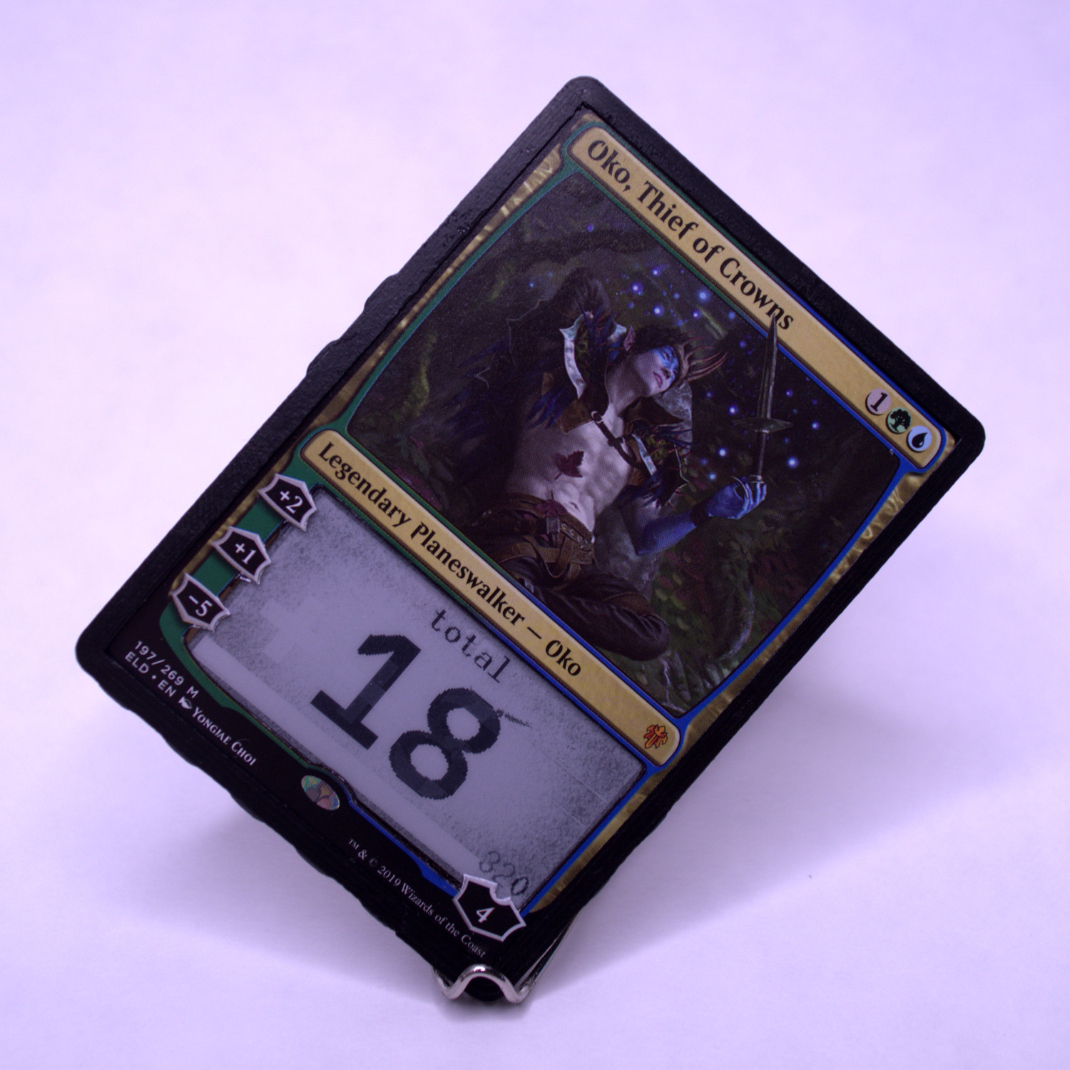
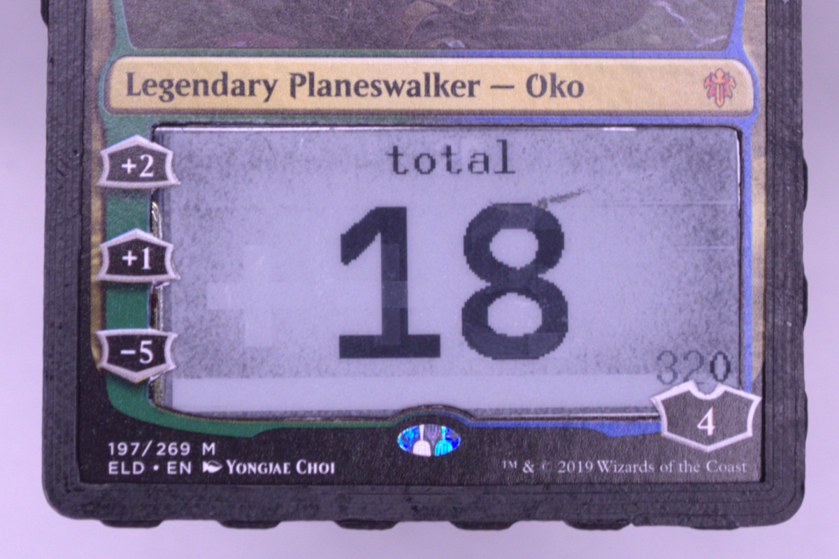
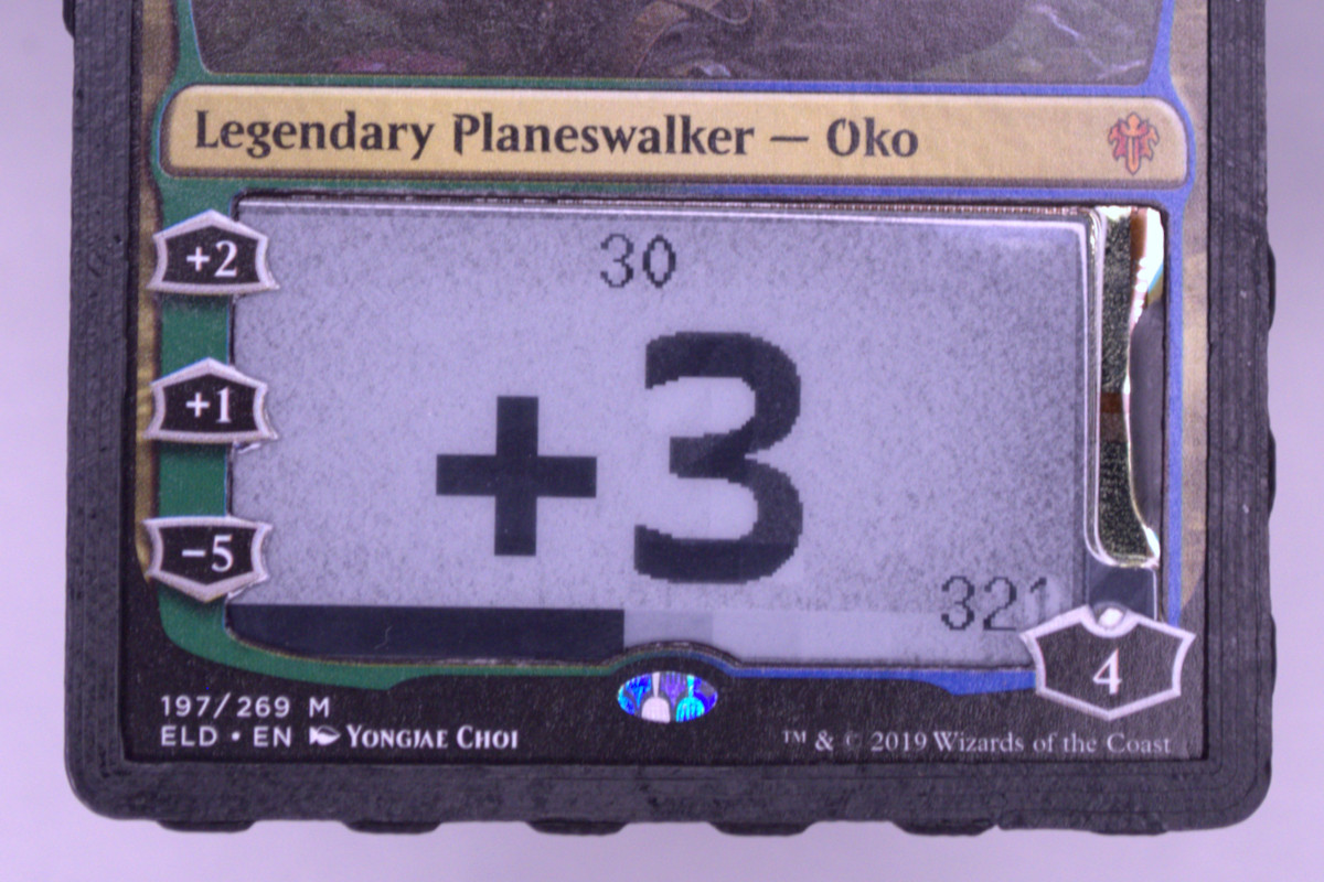
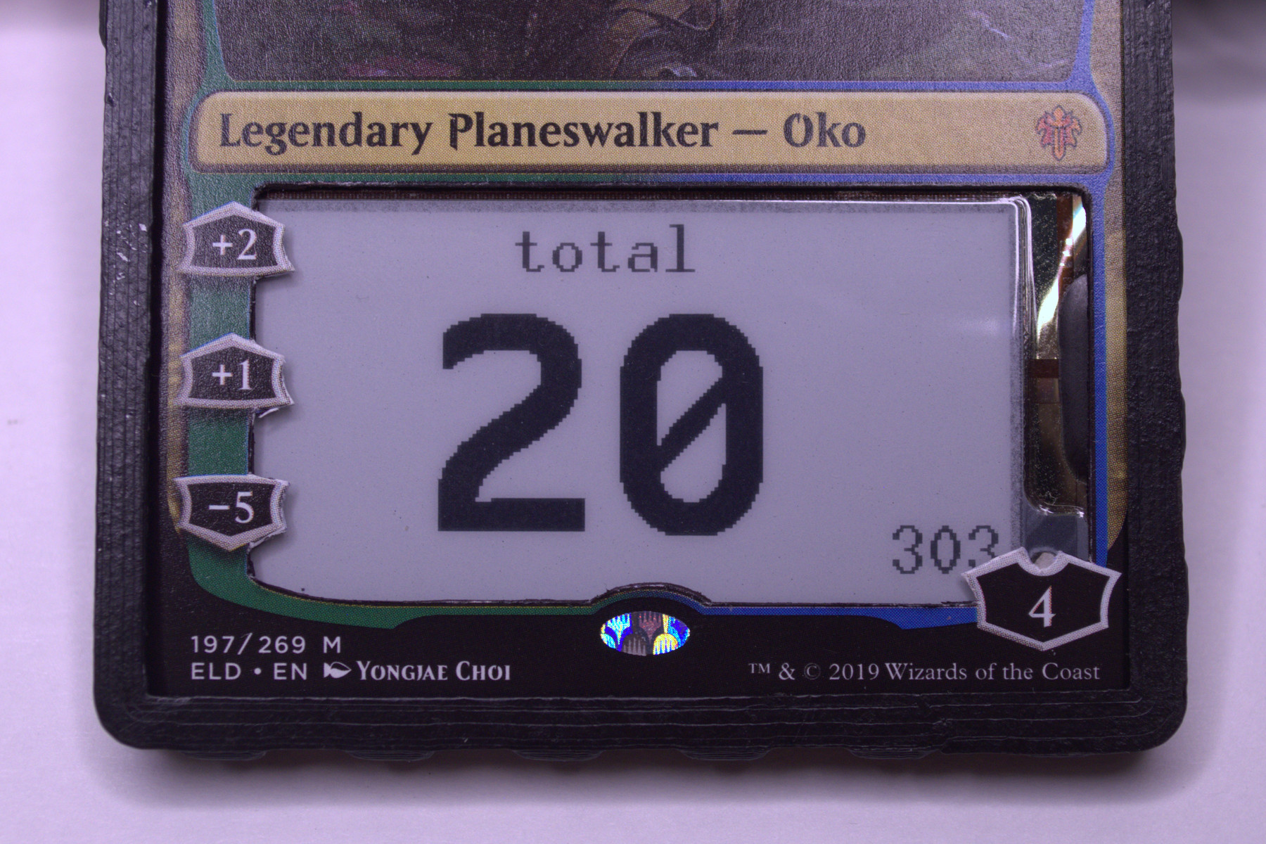
A friend had a cool abacus life counter that he made with his favorite card, so I made a feeble imitation of it using processes and components that were more familiar to me. It's hypothetically usable for keeping track of any integer value in any game, such as a planeswalker's loyalty count or any resource in a board game or tabletop roleplaying game.
I'm not selling them yet, but I'm planning to. To be notified when they're available, click here, fill in your email (if it isn't already done so automatically), and hit "send". Alternatively, you can try to make one yourself using the published schematics and code, in which case I'm happy to help!
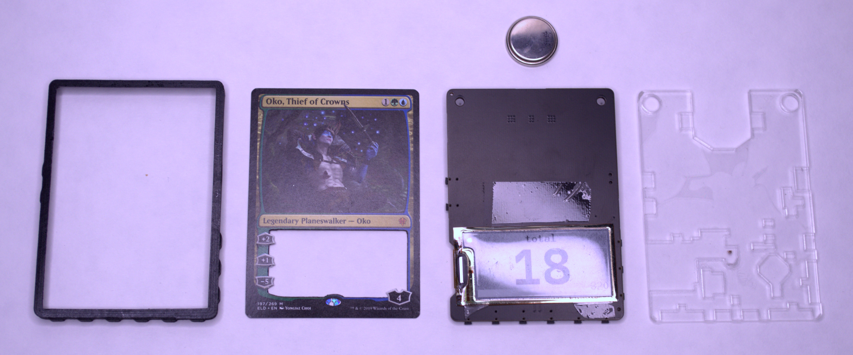
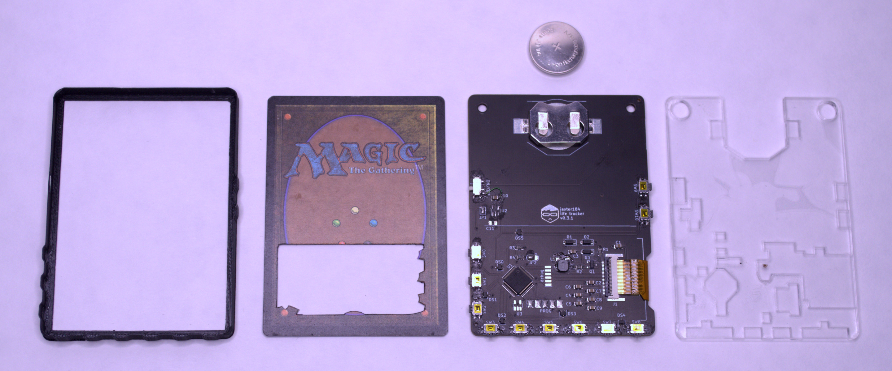
Layers
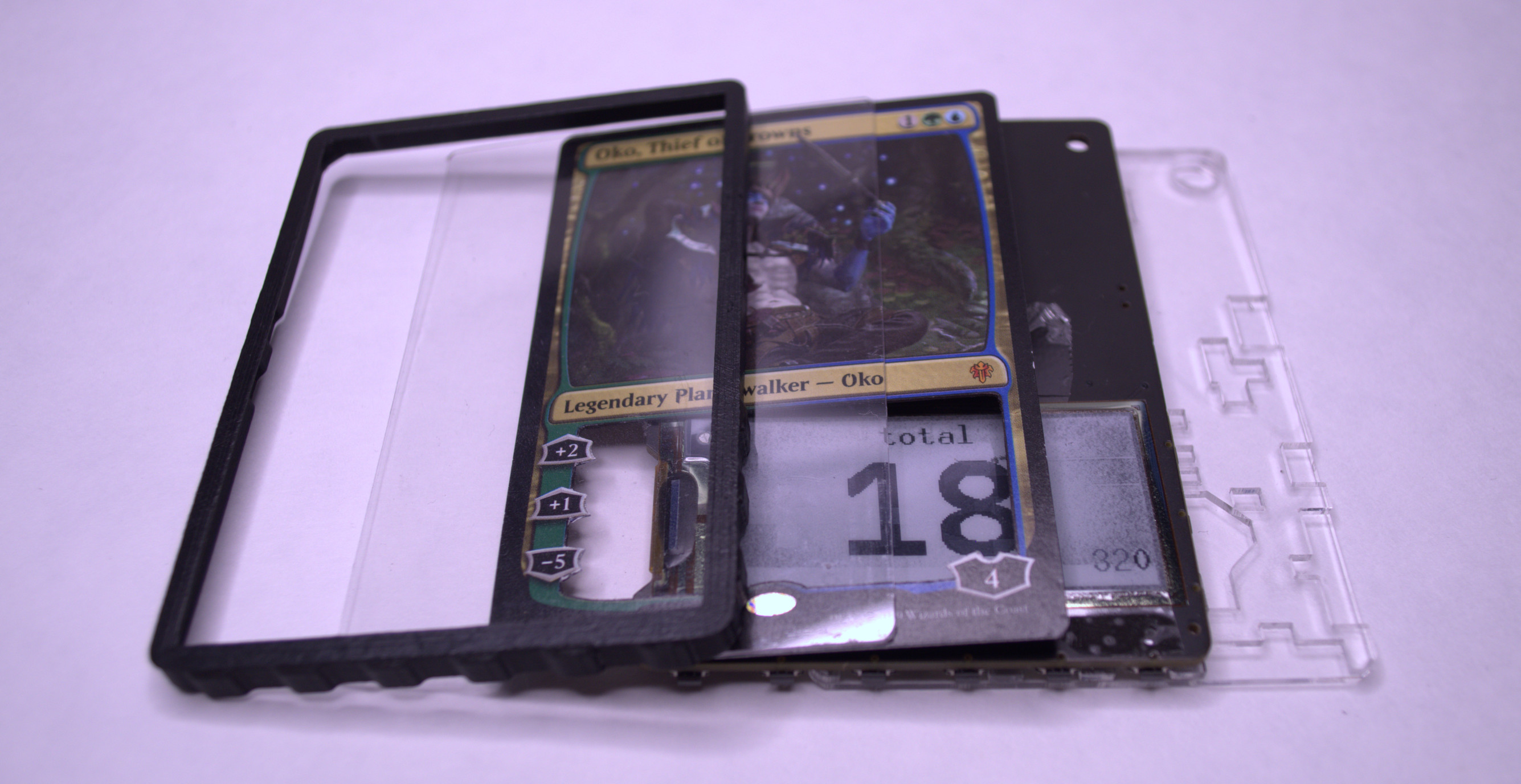
- 3D printed frame with little corner indents to keep everything together
- Thin, hard plastic sheet to protect the card and display
- The card "Oko, Thief of Crowns" from the trading card game, Magic, the Gathering. I bought a bunch of this significantly cheaper card with a similar layout to practice the cutout on.
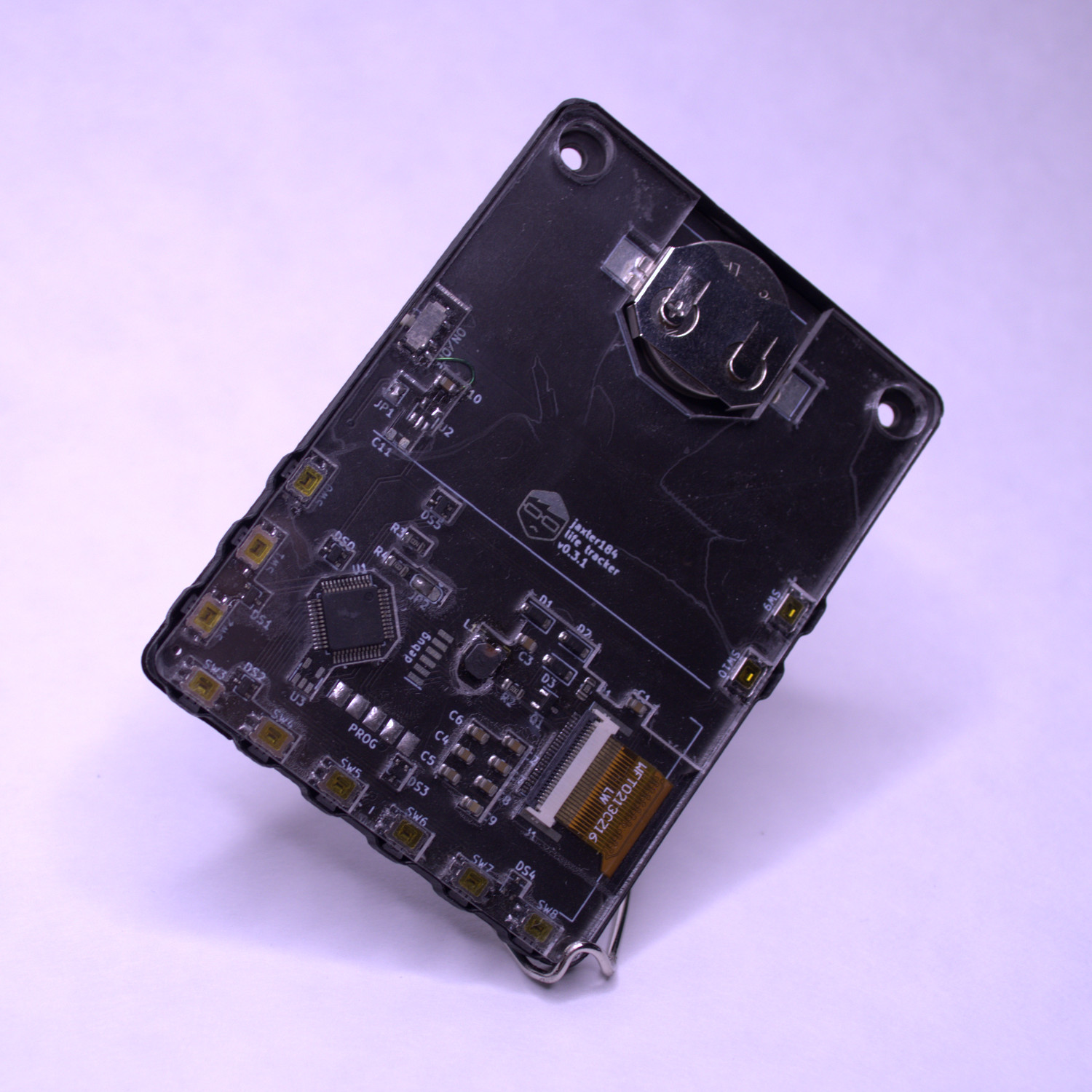
- PCB with an e-ink display, STM32F030C8T6, and side-mounted switches
- Two pieces of laser-cut ~1.5mm acrylic welded together with solvent. Pattern created by manually editing the courtyard output of KiCAD.
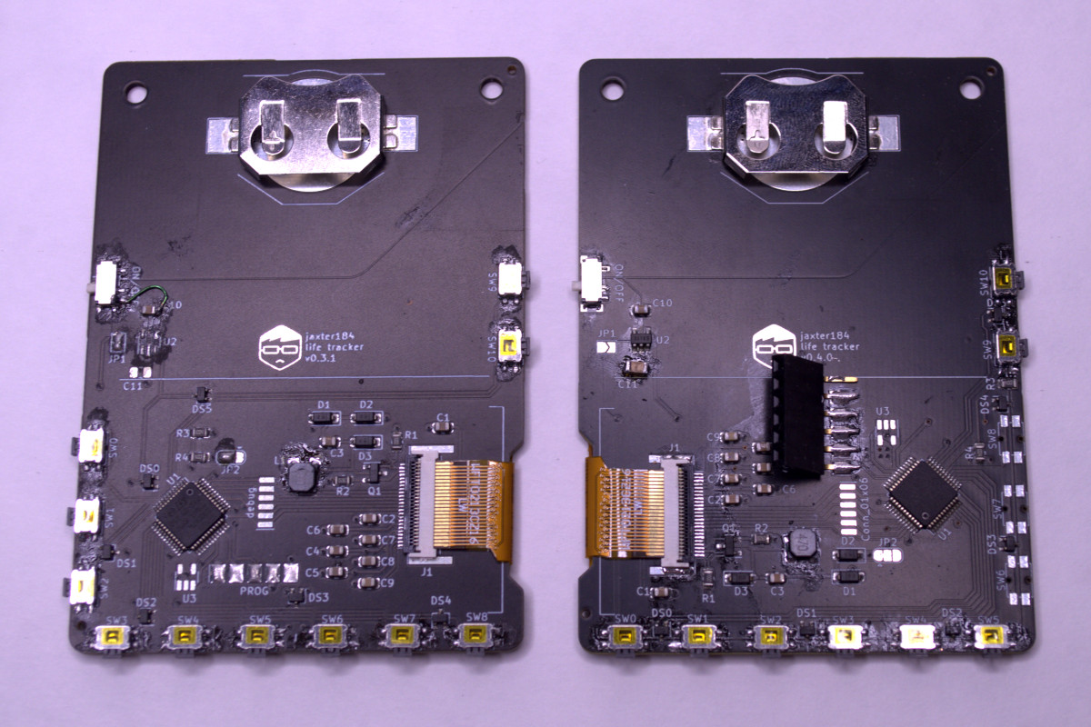
The programming pads are designed for pogo pins, but it's a hassle to hold them on by hand when I'm iterating on code, so I've soldered a header on the one on the right.
Display considerations
The e-paper circuit primarily references the manufacturer's documentation, but I also looked at the Pimoroni Badger 2040 (schematic) and the Waveshare E-Paper Driver HAT.
Old version
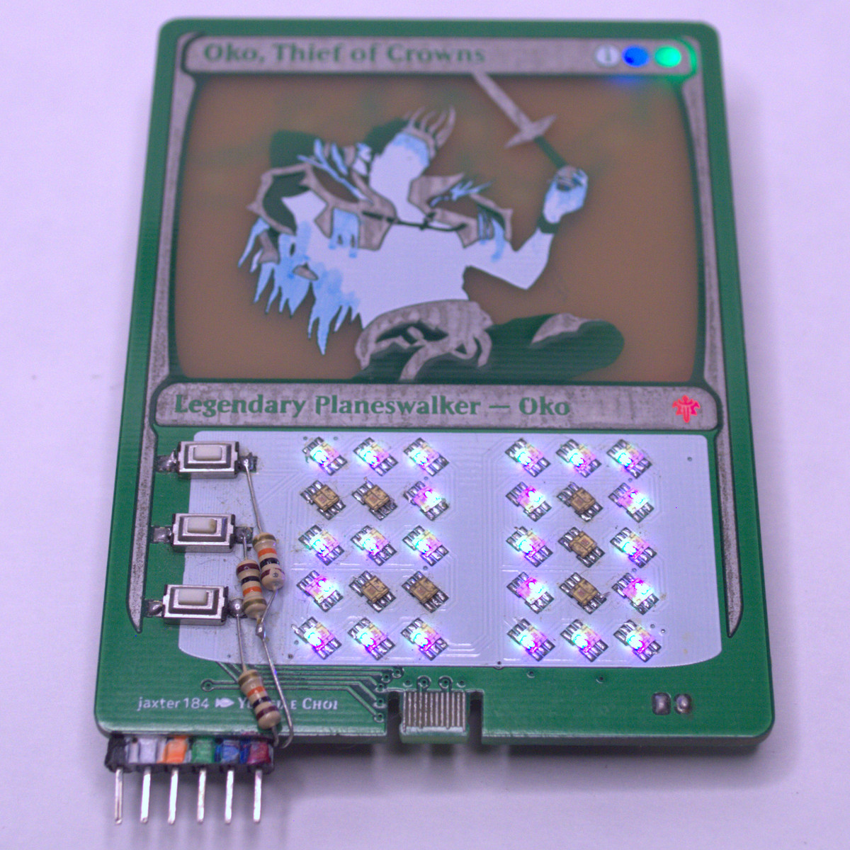
I really liked the rear-illuminated icons, but unfortunately, the LEDs greatly increase the power draw. I'm not sure by exactly how much, but my estimate is that it takes the power on duration from a few days to a few hours. I wanted to use a coin cell in the final version so I wouldn't have to worry about charging or other lithium polymer battery considerations, and the LEDs were pretty much the only thing that drew a lot of power, so they were the first thing to go.
I also thought the PCB art was really cool, and I want to experiment with stuff like halftone/dither and outlines and compensating for the silkscreen leakage, but I'll probably do that on a project that I'm not planning to sell, because I'd prefer to avoid having Wizards of the Coast sic the Pinkertons on me.
Things to try in the future
- USB connector at the top? or the side? or the bottom?
- Add optional LEDs for those who want to use it as an "on" indicator (the e-ink display doesn't have time to change it's display when the unit is powered off)
- See how it fits with Pokémon, Digimon, and Yu-Gi-Oh cards (and maybe others?)
- Make the case on a resin printer. Should be thinner and more precise, and maybe let me make clips like on injection molded parts. If I do the clips, I can probably also redesign the acrylic back to make the clips flush with the back.
- https://github.com/klepas/open-baskerville/tree/master/specimens