This was a project I did in my undergraduate studies to build a digital music controller abstractly based on the bass guitar. The main sensing mechanism was a long row of capacitive touch sensors, intended to sense where along the neck the player was touching, and how much of their finger was touching the surface. In the end, this barely worked, and was a bit clunky to use, and I therefore didn't end up building a full-scale version of the device.
Prior art:
- Someone who made something cooler and more useful and more concretely similar to a bass: https://youtu.be/4m1YorzgxkY
- A commercially available device that (I think) uses the same sensing technology as the previous example: https://maywadenki-os.stores.jp/items/5eef5b521829cd47b90668be
Capacitive touch
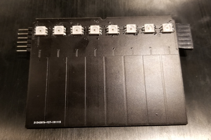
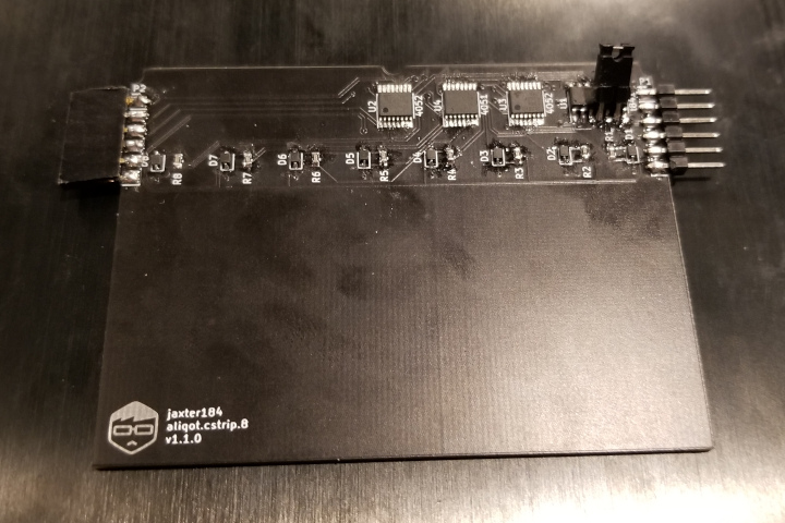
Capacitive touch is one of those things that I had heard a lot about, but never really tried myself. I've had a little capacitive sensing test PCB sitting around for a while, but I never got around to using it. The general idea is that a conductive pad and a finger of varying distance constitutes a capacitor, and by measuring the capacitance at the pad, you can find out how far the finger is from the pad, or how much of the finger is covering it. In retrospect, it was pretty straightforward, but I definitely feel much more comfortable now that I did in the earlier stages of this project.
555
My first approach to measuring the capacitance was an analog circuit. I am most definitely not an analog person. The only analog signals I feel comfortable with are those that either come out of a digital-to-analog converter or one coming into an analog-to-digital converter. However, since the goal of this project was to learn things, getting out of my comfort zone seemed like a good idea.
The idea behind this approach was to set up a 555 timer with a diode and some resistors such that it would pull up the voltage with some RC constant and pull it down with a different RC time constant. I thought that if my clock speed was high enough, I could get a pretty smooth continuous analog signal that I could measure with an ADC. While this did end up working, the range of voltages was too low to be useful, and led to a lot of extra circuitry that could have been avoided by using a different method.
Pulse and read
The more traditional approach to capacitive touch sensing is to connect the pad to an ADC, a GPIO output, and a pull-down resistor. By turning the GPIO on, then setting it to an input (floating), the voltage of the pad will decay at different speeds depending on the capacitance. I thought I was being clever by leaving the diode in from the previous approach, but it turned out to make my measurements a little less accurate, so I probably should have removed it. This is the approach I ended up using, and I think it's accurate enough for decent analog measurements.
Next steps
Something that I'm less than satisfied with is the response curve of the pad. It seems to basically max out as soon as the pad is touched, and I was hoping that it would be more of a gradual change depeding on how much of the pad was covered. To solve this, I could either change the shape and size of the pad or decrease the resistance of the pull-down resistor.
Sound generation
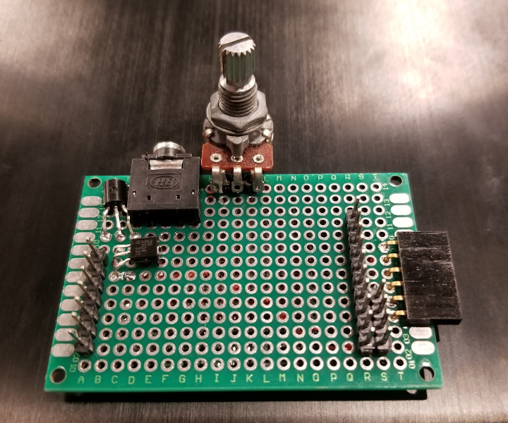
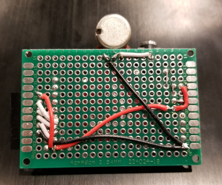
The rough acoustic equivalent of the digital instrument that I hope to design is a bass guitar. In my experience, the easiest way to acoustically simulate a bass guitar sound is to send a PWM waveform through a low-pass filter into a saturator. For now, the plan is to start with the PWM wave. A stretch goal was to design the sound processing in a music programming language called Faust, but like many of my stretch goals, I never really got to that point. I ended up learning Faust anyway for fun, and I think it's really cool, especially since it compiles to C++. Getting a variable pitch PWM output from the TM4C microcontroller was pretty straightforward, and I didn't really run into any huge problems setting that up.
A secondary benefit of using PWM rather than an ADC is that to amplify it, all I need is a single transistor. I eventually want to have more flexible audio outputs, so I'll need a real amplifier in the future, but for now, I've just arranged 2 2N2304 transistors in a Darlington pair configuration.
Switches
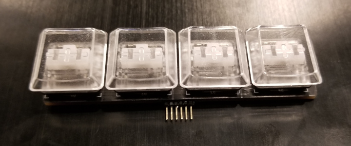
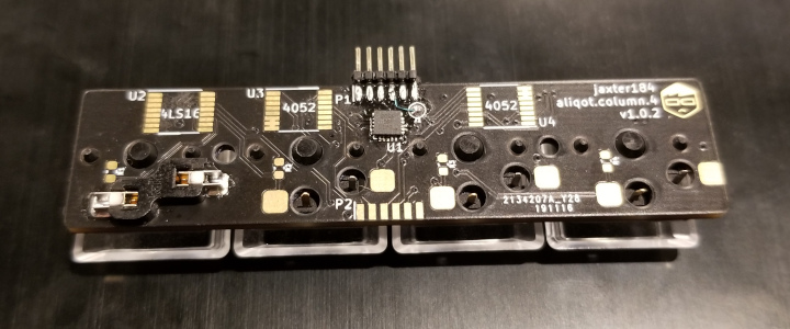
In the time I spent thinking about instrument interfaces and which ones work and which ones don't, one of the conclusions I came to was that while pitch control is generally easier to implement as a non-tactile experience, rhythm, or more generally, volume, is almost necessarily tactile. For example, a violin can be split into the fingerboard, which controls pitch, and the bow, which mostly controls volume. The fingerboard feels about the same at low pitches as it does at higher pitches. On the other hand (pun intended), the bow transmits the resistance of the hairs against the string, increasing as you apply more pressure or move the bow faster. The piano is similar in that different pitches mostly feel the same to play, but different volumes feel different (assuming you're only playing with one finger). This distinction is true to some extent for most instruments, though it is unclear if that is due to how instruments have evolved over time or if it is a physical restriction of acoustic instruments. Either way, what is most intuitive at this point in time is for rhythmic elements to be tactile, which is why I've included switches as the sound triggering element of the instrument.
Shift registers
I'm usually pretty good about reading datasheets. I'm not sure exactly what happened, but when I was making my PCB, I thought that the pin labelled DS (for Data Serial) was the serialized output of the shift register. It turns out that it's the input, which I figured out after not getting any output until accidentally probing the adjacent pin. I think if the serial in and serial out pins weren't next to each other, I would have spent much longer trying to figure out what was wrong.
QFN
The more keen-eyed readers will notice that the above PCB is unpopulated except for the switches and one integrated circuit. This is because it is a more recent revision that I haven't yet gotten to work. The main difference between this revision and the last one is that I swapped out the SOIC chip for a QFN one. This allowed me to make the board much smaller, but also much more difficult to debug. Because there is no way to probe whether the pad on the PCB is conducting to the pad on the IC, I have been having trouble figuring out why the boards are having issues being programmed. For now, I've decided to ignore it because I have a working board with essentially the same circuit.
Mechanical Design
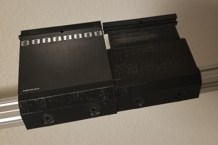
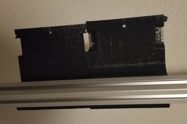
Pictured above are two revisions of the 3D printed bracket part that I made to hold the capacitive sensing PCB, both made in FreeCAD. The part was built to fit onto a piece of 2020 aluminum extrusion. I'm a big fan of aluminum extrusion because it's very easy to use. In this case, all I have to do is cut it to an arbitrary length and attach stuff to it. I don't even need a second piece. I've had issues in the past where the structures I've build were too weak to hold their own weight, but because this is lighter and simpler, I didn't run into that problem. The main feature of the newer revision is that it has registration holes to align the loose end of the bracket with the bracket below. While the 3D printed part is very rigid (material is PETG), even a small change in alignment could tear the pads off one of the boards since they are soldered together on the back.
The framework
The goal was to create a framework that would allow hot-swappable modules to send continuous streams of low latency analog-to-digital converted data. The details of the communication framework are probably enough to fill an entire other blog post. In fact, I probably will write another one at some point that goes into why I made all the design decisions I did. For now, though, I'll just outline how it works.
When the modules are initially connected, they are detected by their parent module and registered with the main module (in this case, the TM4C that is generating the sound). This registration value is prepended to all of the communication from this module to tell the main module where each set of data is coming from.
The first byte of each communication from a child module to its parent is the number of modules that are sending data in a given set. Each module's data then follows one after another. The first byte of a module's data is its address, and the second byte is how many values are being sent as data. The switch modules send 1 byte and the capacitive sensing modules send 8 bytes.
The example below is what is sent to the TM4C from a capacitive sensing module, which is connected to a switch module such that TM4C <- capacitive_sensing <- switches.
byte #:               1    2    3    4    5    6    7    8    9   10   11   12   13   14
hexadecimal value: 0x02 0x01 0x08 0x01 0x01 0x01 0x01 0x01 0x01 0x01 0x01 0x02 0x01 0x0A
Byte descriptions:
- 1st byte: # of modules
- 2nd byte: Address of the first module
- 3rd byte: # of bytes of data in the first module
- [4:11]th byte: Data
- 12th byte: Address of the second module
- 13th byte: # of bytes of data in the second module
- 14th byte: Data
Byte addresses are one-indexed (as opposed to zero-indexed)and all data has 1 added to it because a 0 byte indicates that data is not yet ready to be send. I wouldn't need to do this if I was using a multi-leader bus, but I'm not using one, so I do need to. Either that or I would have to somehow indicate whether or not a byte is ready to be sent.
Circular buffers!
The way the framework is set up, I need two buffers
for input and output data. Because these buffers are
continuously filled and emptied as a FIFO queue, it made sense
to make it a circular buffer. In the repository, this is implemented in
modport.c.
One of the goofs that I ran into was that I was incrementing the
position of the queue when I added elements to it rather than its
length. Oops.
An addendum
While circular buffers are great, and worked fine for this application, I think it actually would have made more sense to make it a ping-pong buffer, as one way to implement the communication framework is to make the output buffer a concatenation of the input buffer and the additional data for the module, with one modification at the beginning of the input queue. I think I would also have to change the communication protocol to send the number of bytes rather than the number of modules, which limits throughput more than I would like. Also, I like the idea that the data packet can be indefinite, so I'll probably leave it as is until I hit a performance obstacle.
Obstacles
I spent much longer than I should have trying to figure out why the protocol was working with the switches, but not the capacitive sensing. A third of the time was because the initialization was commented out, and the remainder is because the initializations have to be in a particular order for some reason.
The only thing that I haven't figured out yet is why the TM4C (the main module that produces the sound) won't communicate over SPI with its child modules. Serial communications are definitely being initiated, but there is no data being transferred between the two microcontrollers. I suspect it has something to do with the fact that TI uses SSI, which has Rx and Tx, while the ATtiny uses SPI, which has LOMI and LIMO. Either that or it's a 3.3v vs 5v issue. Now that I think about it, it's almost certainly the latter.
an aside regarding the silly name
The goal of this project was to create a modular instrument framework that I could use in the future to more quickly produce digital instruments. I spent roughly 20 minutes jumping around on Wikipedia until I ended up on the entry for aliquot stringing, and after seeing the keywords "several" and "sympathetically", I figured it would be a good name for the project given the goals. I also took out a letter for better search engine optimization.
Closing thoughts
Though I didn't end up with a fully functional instrument, I achieved all but one of my goals. I have a thing that takes an input and a thing that makes sound, and now all I need to do is put them together. Based on my initial tests, the latency in communication between modules is pretty much negligible. I haven't tested it with more than 4 modules, but the results seemed negligible at a small scale, and I'm fairly certain that most of the observed latency was caused by communication with the LEDs rather than the communication between the modules themselves. One thing to test in the future is using a bus protocol like CAN or I2C (preferably CAN due to bidirectional multi-leader capabilities) rather than a serial protocol, as it could help with scalability.